
Structured cabling and cross-connects
Fixed splice panel
19-inch / 1UEmpty or populated
- Housing
- SPCC steel with flip-top cover
- Management
- Splice tray, side clamp and front cord manager
- Loading
- Adapters, pigtails and splice accessories itemized
INFRASTRUCTURE SYSTEMS ● OPTICAL DISTRIBUTION
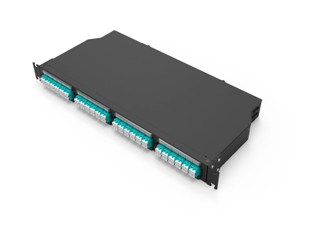
Fixed splice panels and modular 1U distribution frames for empty, adapter-loaded and pre-terminated applications. Compare fiber capacity, module positions, physical dimensions and component interfaces.
PRODUCT SCOPE
Specify the housing and then state what is loaded inside it. Capacity, adapter count and pre-terminated fiber count are separate values.
PRODUCT RANGE
Explore formats and details ↗FORMATS / TECHNICAL SPECIFICATIONS
Physical specifications, supply details and application fit—organized for a faster technical comparison.
Structured cabling and cross-connects
High-density data-room distribution
Dense interconnect and trunk aggregation
SPECIFICATION CHECKPOINTS
Singlemode or multimode
LC, SC or MPO-based module; polish by project
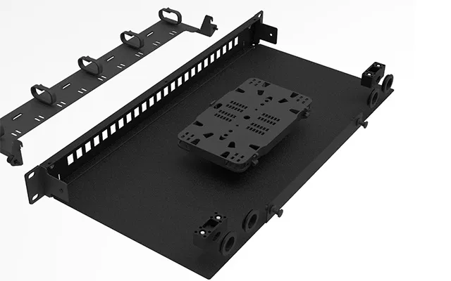
Splice tray, bend radius, entry and front cord path
Insertion/return-loss targets and report format
APPLICATIONS / SELECTION PATHS
Explore the application, product interface and configuration decisions that matter to the actual installation.
SPECIFICATION PATH
Start with a 1U fixed or modular panel, then define cable entry, splice management and the actual loaded port schedule.
KEY SELECTION DECISIONS
An empty enclosure, adapter-loaded panel and complete pre-terminated kit are different quotation scopes.
Singlemode/multimode, LC/SC/MPO, polish and adapter color must be specified against the actual platform.
State insertion/return-loss targets and the required test-report format for the assembled item.
TECHNICAL DATA / SELECTION MATRIX
An empty enclosure and a loaded assembly are different products. Specify adapters, cassettes, pigtails and termination separately.
!96F and 144F are published platform capacities. The populated fiber count is determined by the selected module and loading schedule.
SELECT / VALIDATE
Open each item for the engineering and documentation decisions that matter to this family.
Singlemode or multimode; LC, SC and MPO-based configurations where the selected platform supports them.
List each adapter, cassette, splice tray, pigtail and pre-terminated assembly instead of quoting only a port count.
State the connector polish, insertion/return-loss targets and required test-report format for the assembled item.
FOR A USABLE RFQ
Send rack height, fiber count, connector type, polish, loaded/empty preference and test requirements to receive a configuration-specific quote.